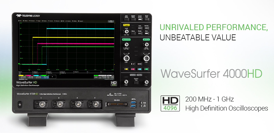
WaveSurfer 4000HD (200MHz-1GHz) 高解析度示波器 (12 bits)
上架時間
WaveSurfer 4054HD / WS4054HD
500 MHz, 2.5 GS/s, 4 Ch, 12.5 Mpts/Ch High Definition Oscilloscope with 12.1” capacitive touch screen
商品介紹
Datasheet/規格書
Vertical - Analog Channels |
|
| Analog Bandwidth (Max) | 500 MHz |
| Bandwidth | 10.74"H x 14.96"W x 6.30"D (273 mm x 380 mm x 160 mm) |
| Analog Bandwidth @ 50 Ω (-3 dB) (ProBus Input) | 500 MHz |
| Analog Bandwidth @ 1 MΩ (-3 dB) (ProBus Input) | 500 MHz |
| Rise Time (10-90%, 50 Ω) | 700 ps |
| Input Channels | 4 |
| Input Channels | 11.7 lbs (5.3 kg) |
| Vertical Resolution | 14 bits; up to 15 bits with enhanced resolution (ERES) |
| Vertical Resolution | 20.06 lbs (9.1 kg) |
| Effective Number of Bits (ENOB) | 8.5 |
| Vertical Noise Floor (1 mV/div) | 88 uVrms |
| Vertical Noise Floor (2 mV/div) | 88 uVrms |
| Vertical Noise Floor (5 mV/div) | 88 uVrms |
| Vertical Noise Floor (10 mV/div) | 93 uVrms |
| Vertical Noise Floor (20 mV/div) | 116 uVrms |
| Vertical Noise Floor (50 mV/div) | 212 uVrms |
| Vertical Noise Floor (100 mV/div) | 352 uVrms |
| Vertical Noise Floor (200 mV/div) | 1.11 mVrms |
| Vertical Noise Floor (500 mV/div) | 2.10 mVrms |
| Vertical Noise Floor (1 V/div) | 3.51 mVrms |
| Sensitivity | 1 MΩ: 1 mV/div - 10 V/div, fully variable; 50 Ω: 1 mV/div - 1 V/div, fully variable |
| DC Vertical Gain Accuracy (Gain Component of DC Accuracy) | ±(0.5%) FS, offset at 0 V |
| Channel-Channel Isolation | DC - 200 MHz: 60 dB (>1000:1) 200 MHz - 500 MHz: 50 dB (>300:1) (For any two ProBus input channels, same v/div settings, typical) |
| Offset Range | 50 Ω ±1.6 V @ 1 mV - 4.95 mV/div ±4 V @ 5 mV - 9.9 mV/div ±8 V @ 10 mV - 19.8 mV/div ±10 V @ 20 mV - 1 V/div 1 MΩ ±1.6 V @ 1 mV - 4.95 mV/div ±4 V @ 5 mV - 9.9 mV/div ±8 V @ 10 mV - 19.8 mV/div ±16 V @ 20 mV - 100 mV/div ±80 V @ 102 mV - 198 mV/div ±160 V @ 200 mV - 1 V/div ±400 V @ 1.02 V - 10 V/div |
| DC Vertical Offset Accuracy | ±(1.0% of offset setting + 0.5% FS + 0.02% of max offset + 1mV) |
| Maximum Input Voltage | 50 Ω: 5 Vrms, 1 MΩ: 400 V max (DC + Peak AC ≤ 10 kHz) |
| Input Coupling | 1 MΩ: AC, DC, GND; 50 Ω: DC, GND |
| Input Impedance | 50 Ω ± 2.0% or 1 MΩ || 15 pF |
| Bandwidth Limiters | 20MHz, 200MHz |
| Rescaling | Electrical: volts, amps |
Horizontal - Analog Channels |
|
| Timebases | Internal timebase common to 4 input channels |
| Acquisition Modes | Real-time, Roll, Average, Sequence |
| Time/Division Range | 500 ps/div - 100 s/div Roll Mode available at ≥ 50 ms/div |
| Clock Accuracy | +/-2.5ppm + 1.0ppm/year from calibration |
| Channel-Channel Deskew Range | < 5us/div, ± 100 ns, each channel ≥ 5us/div, ± (Tdiv x 0.04), each channel |
Acquisition - Analog Channels |
|
| Sample Rate | CE Compliant, UL and cUL listed; conforms to UL 61010-1 (3rd Edition), UL 61010-2-030 (1st Edition) CAN/CSA C22.2 No. 61010-1-12 |
| Maximum Acquisition Memory | 3-year warranty; calibration recommended annually. Optional service programs include extended warranty, upgrades, and calibration services. |
| Sample Rate (Single-shot) | 5 GS/s on 2 Ch 2.5 GS/s on 4 Ch |
| Memory Length (4 Ch / 2 Ch / 1Ch) (Number of Segments) |
12.5M / 25M (1,000) |
| Intersegment Time | 1 µs |
| Enhanced Resolution (ERES) | From 12.5 to 15 bits vertical resolution |
| Envelope (Extrema) | Envelope, floor, or roof for up to 1 million sweeps |
Vertical, Horizontal, Acquisition - Digital Channels |
|
| Maximum Input Frequency | 125 MHz |
| Minimum Detectable Pulse Width | 4 ns |
| Input Channels | 16 Digital channels (with WS4KHD-MSO option) |
| Input Impedance (Flying Leads) | 100 kΩ || 5 pF |
| Input Dynamic Range | ±20V |
| Maximum Input Voltage | ±30V Peak |
| Maximum Input Voltage Swing | 500mVpp |
| Threshold Groupings | Pod 2: D15 - D8, Pod 1: D7 - D0 |
| Threshold Selections | TTL (+1.4V), 5V CMOS (+2.5V), ECL (-1.3V), or User Defined |
| Threshold Accuracy | ±(3% of threshold setting + 100mV) |
| User Defined Threshold Range | ±10V in 20 mV steps |
| Sample Rate | 500 MS/s |
| Record Length | 12.5 MS - 16 Channels |
| Channel-to-Channel Skew | ±(1 digital sample) |
Triggering System |
|
| Max Trigger Frequency (C1-C4, Aux In, SMART Trigger) | 500MHz |
| Modes | Normal, Auto, Single, Stop |
| Sources | Ch 1 - Ch 4, EXT, EXT/5, AC Line |
| Coupling | DC, AC, HFRej, LFRej |
| Pre-trigger Delay | 0-100% of memory size |
| Post-trigger Delay | 0 - 10,000 Divisions |
| Hold-off | 10 ns up to 20s or from 1 to 100,000,000 |
| Trigger and Interpolator Jitter | ≤ 8 psrms (typical) |
| Internal Trigger Level Range | ±4.1 Divisions |
| External Trigger Level Range | Ext: ±0.61 V, EXT/5: ±3.05 V |
| Maximum Trigger Rate | ≤ 175,000 waveforms/second |
| Trigger Sensitivity with Edge Trigger ProBus Inputs | 0.9 division: DC - 10 MHz 1 division: 10 MHz - 200 MHz |
| Trigger Sensitivity with Edge Trigger (Aux Input) | Ext: 200 mV from DC to 10 MHz 300 mV from 10 MHz to 200 MHz Ext/5: 1 V from DC to 10 MHz 1.5 V from 10 MHz to 200 MHz |
Trigger Types |
|
| Edge | Triggers when signal meets slope (positive, negative, or either) and level condition. |
| Width | Triggers on positive or negative glitches with selectable widths. minimum width 2 ns, Maximum Width: 20 s |
| Window | Triggers when signal exits a window defined by adjustable thresholds |
| Pattern | Logic combination (AND, NAND, OR, NOR) of 5 inputs (4 channels and external trigger input). Each source can be high, low, or don’t care. The High and Low level can be selected independently. Triggers at start or end of the pattern. |
| TV-Composite Video | Triggers NTSC or PAL with selectable line and field; HDTV (720p, 1080i, 1080p) with selectable frame rate (50 or 60 Hz) and Line; or CUSTOM with selectable Fields (1-8), Lines (up to 2000), Frame Rates (25, 30, 50, or 60 Hz), Interlacing (1:1, 2:1, 4:1, 8:1), or Synch Pulse Slope (Positive or Negative). |
| Runt | Trigger on positive or negative runts defined by two voltage limits and two time limits. Select between 1 ns and 20 ns. |
| Slew Rate | Trigger on edge rates. Select limits for dV, dt, and slope. Select edge limits between 1 ns and 20 ns. |
| Interval | Triggers on intervals selectable between 1 ns and 20 s. |
| Dropout | Triggers if signal drops out for longer than selected time between 1 ns and 20 s. |
| Multi-Stage: Qualified (Timeout or State/Edge Qualified) | Triggers on any input source only if a defined state or edge occurred on another input source. Delay between sources is selectable by time. |
| Triggers with Exclusion Technology | Trigger on intermittent faults by specifying the expected behavior and triggering when that condition is not met |
Low Speed Serial Protocol Trigger (Optional) |
|
| Supported Protocols | I2C, SPI (SPI, SSPI, SIOP), UART-RS232, CAN1.1, CAN2.0, CAN FD, LIN, FlexRay, AudioBus (I2S, LJ, RJ, TDM) |
Math Tools |
|
| Math Functionality | Display up to 6 measurement parameters together with statistics, including mean, minimum, maximum, standard deviation, and total number. Each occurrence of each parameter is measured and added to the statistics table. Histicons provide a fast, dynamic view of parameters and waveshape characteristics. Parameter gates define the location for measurement on the source waveform. |
| Math Operators - Basic Math | Delay (from trigger, 50%), Duty Cycle, Fall Time (90-10, 80-20), Frequency, Period, Δ Period, Phase, Rise Time (10-90, 20-80), Skew, Width+, Width- |
| Math Operators - Digital (incl. with MSO models/options) | Amplitude, Base, Maximum, Mean, Minimum, Peak-to-Peak, RMS, Std. Deviation, Top. |
| Math Operators - Filters | Area, Base, Fall Time (90-10, 80-20), Overshoot (positive, negative), Rise Time (10-90, 80-20), Top, Width+, Width- |
| Math Operators - Functions | Display up to 2 math functions traces (F1-F2). The easy-to-use graphical interface simplifies setup of up to two operations on each function trace, and function traces can be chained together to perform math-on-math. |
| Math Operators - Other | Average (summed), Average (continuous), Difference (-), Envelope, Floor, Invert (negate), Product (x), Ratio (/), Reciprocal, Rescale (with units), Roof, Sum (+). |
Pass/Fail Testing |
|
| Pass/Fail Testing | Enhanced resolution (to 15 bits vertical) |
Three-phase Electrical and Mechanical Motor Drive Analysis Software |
|
| Setup Capability | FFT (power spectrum, magnitude), up to 500 kpts record length. Select from Rectangular, VonHann, Hamming, FlatTop and Blackman Harris windows. |
| Numerics Measurement Table Selections | Derivative, Integral, Invert (negate), Rescale (with units), Square, Square root, Zoom (identity). |
| Per-cycle "Synthesized" Waveforms and Statistics | Trend (datalog) of up to 1000 measurement parameters |
| Harmonics Calculation Option (MDA800-HARMONICS) | Mask Test (pre-defined or user-defined mask, waveform All In, All Out, Any In, or Any Out conditions) with following THEN Save (waveforms), Stop, Alarm, (send) Pulse, Hardcopy (send email, save screen image, save to clipboard, send to printer), or (save) LabNotebook. |
Integrated Second Display |
|
| Size | Color 12.1" widescreen capacitive touch screen |
| Resolution | 1200 x 800 |
LeCroy WaveStream™ Fast Viewing Mode |
|
| Intensity | Display a maximum of 8 traces. Simultaneously display channel, zoom, memory and math traces. |
| Types | Auto, Single,X-Y, Single+X-Y |
| Number of Channels | Sample dots joined, or sample dots only |
High Speed Digitizer Output (Option) |
|
| Type | Variable saturation levels; stores each trace’s persistence data in memory |
| Transfer Rate | Select analog or color |
| Output Protocol | Activate persistence on all traces |
| Control Protocol | Select from 1.00 s to infinity |
Calibration |
|
| Auto Calibration | Display up to 8 Zooms |
| Calibration Stability | 4 active waveform memory traces (M1-M4) store 16 bit/point full length waveforms. Waveforms can be stored on the internal microSD card or external USB device, limited only by the data storage media capacity |
Processor/CPU |
|
| Type | Store to the internal microSD, over the network, or to a USB-connected peripheral device. |
| Processor Memory | Automatically sets timebase, trigger, and sensitivity to display a wide range of repetitive signals |
| Operating System | Automatically sets the vertical sensitivity and offset for the selected channel to display a waveform with the maximum dynamic range |
| Oscilloscope Operating Software | Ensures specified DC and timing accuracy is maintained for 1 year minimum. |
| Real Time Clock | Calibration ensured within +/-5°C operating temperature. Manual calibration may be invoked if outside this temperature range. |
Connectivity |
|
| Ethernet Port | TI AM5728 Sitara Processor |
| USB Host Ports | 2 GB |
| USB Device Port | Microsoft Windows CE |
| GPIB Port (optional) | Teledyne LeCroy MAUI™ |
| External Monitor Port | Date and time displayed with waveform in hardcopy files. SNTP support to synchronize to precision internal clocks. |
| Remote Control | Supports 10/100BaseT Ethernet interface (RJ45 port) |
| Network Communication Standard | 2 side USB 2.0 ports, 2 front USB 3.1 Gen 1 ports |
| LSIB Port (optional) | 1 port - USBTMC over USB 2.0 |
| Serial Port | Supports IEEE - 488.2 (External) |
| Peripheral Bus | 1 x HDMI, supports up to 1280x800 |
Auxiliary Input |
|
| Signal Types | Via Windows Automation, or via LeCroy Remote Command Set |
| Coupling | VXI-11 or VICP, LXI Compatible |
Auxiliary Output |
|
| Control Signals | Select External Trigger on the rear panel |
| Connector Type | 52 Ω: DC; 1 MΩ: DC |
Probes |
|
| Probes | 50 Ω: 5 Vrms; 1 MΩ: 250 Vmax (DC + Peak AC ≤ 10 kHz) |
| Probe System | Always Trig Out |
| Scale Factors | 3.3 V into 1 MΩ pulse > 1.3 ms |
| Calibration Output | Trigger out |
Power Requirements |
|
| Voltage | BNC, located on back |
| Nominal Power Consumption | Qty. (4) ÷10 Passive Probes |
| Max. Power Consumption | ProBus. Automatically detects and supports a variety of compatible probes |
Environmental |
|
| Temperature (Operating) | Automatically or manually selected depending on probe used |
| Temperature (Non-Operating) | Default is 1kHz square wave, 3.3Vp-p (typical), output to probe hook. Settable from 500 Hz to 1 MHz square wave |
| Humidity (Operating) | 100-240 VAC ±10% at 50-60 ±10% Hz; 110-120 VAC ±10% at 400 ±5% Hz; Automatic AC Voltage Selection |
| Altitude (Operating) | 150 VA |
| Altitude (Non-Operating) | 0 °C to 50 °C |
| Random Vibration (Operating) | -30 °C to 70 °C |
| Random Vibration (Non-Operating) | 5% to 90% relative humidity (non-condensing) up to ≤ +31 °C. Upper limit derates to 50% relative humidity (non-condensing) at +50 °C. |
| Functional Shock | 5% to 95% relative humidity (non-condensing) as tested per MIL-PRF-28800F |
Size and Weight |
|
| Dimensions (HWD) | Up to 10,000 ft. (3048 m) at or below +30 °C |
| Weight | Up to 40,000 ft. (12,192 m) |
Mixed Signal Option |
| WS4KHD-MSO Mixed Signal Option for WaveSurfer 4000HD (includes probe, accessories, and license) |
Mixed Signal Solutions |
| WS4KHD-MSO-LICENSE MSO License for WaveSurfer 4000HD (MSO Probe Not Included) |
Remote Control/Network Options |
| USB2-GPIB External USB 2.0 to GPIB IEEE 488.2 adapter |
Power Analysis Software |
| WS4KHD-PWR Power Analysis Option for WaveSurfer 4000HD |
Serial Trigger and Decode |
| WS4KHD-AUDIO TD AudioBus trigger and decode option for WaveSurfer 4000HD |
| WS4KHD-AUTO TD Automotive SW bundle (CAN, CAN FD, LIN & FlexRay) for WaveSurfer 4000HD |
| WS4KHD-EMB TD Embedded SW bundle (I2C, SPI, UART/RS232) for WaveSurfer 4000HD |
Other Software Options |
| WS4KHD-FG Function Generator for WaveSurfer 4000HD |
Miscellaneous |
| WS4KHD-SOFTCASE WaveSurfer 4000HD Softcase |
| WS4KHD-RACK WaveSurfer 4000HD Rackmount kit |